
Life-size cutout: plans, assembly and stability
Published on 17 November 2026
A life-size cutout must stand upright without distracting the eye, assemble without tools and travel flat. This article details the system we use: two feet, a ballast tray and a panel tilted backwards at 15°. To order, see the page life-size cutout.
What you receive
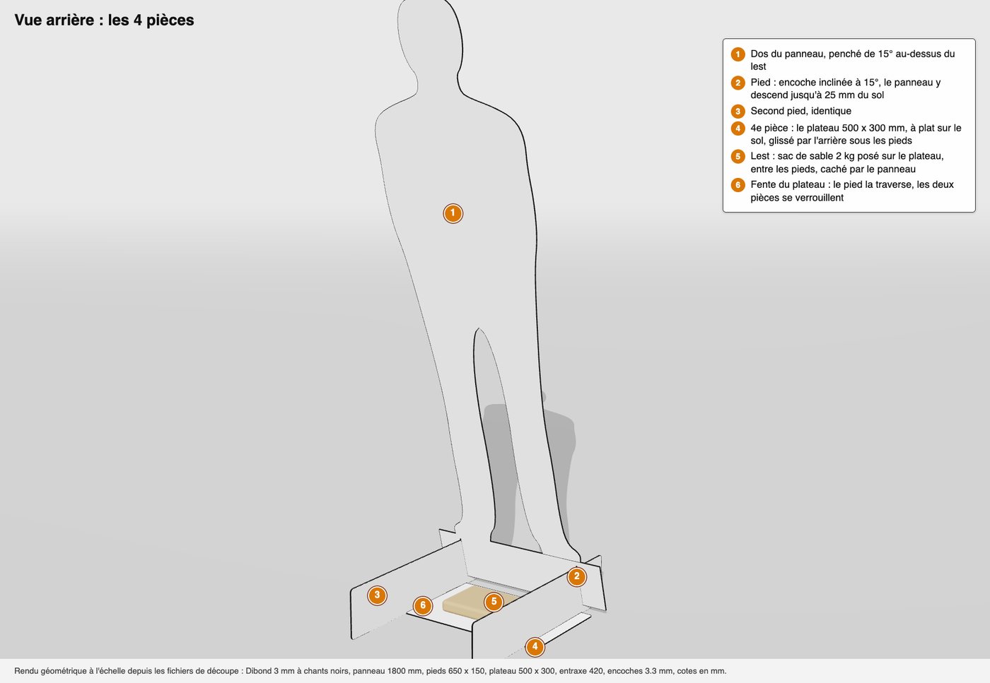
Four contour-cut parts from the same sheet, delivered flat:
- le silhouette panel printed, up to 180 cm high;
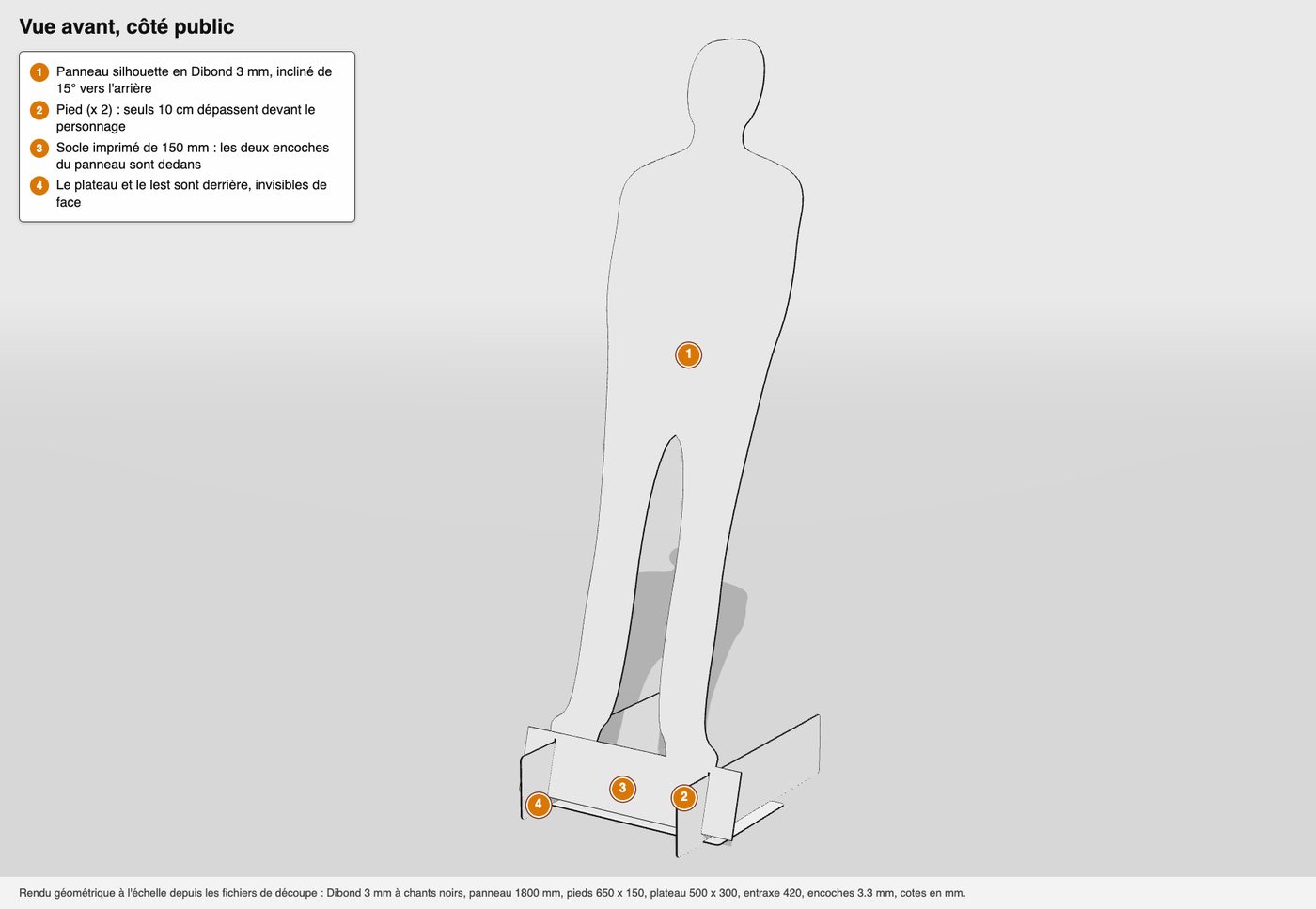
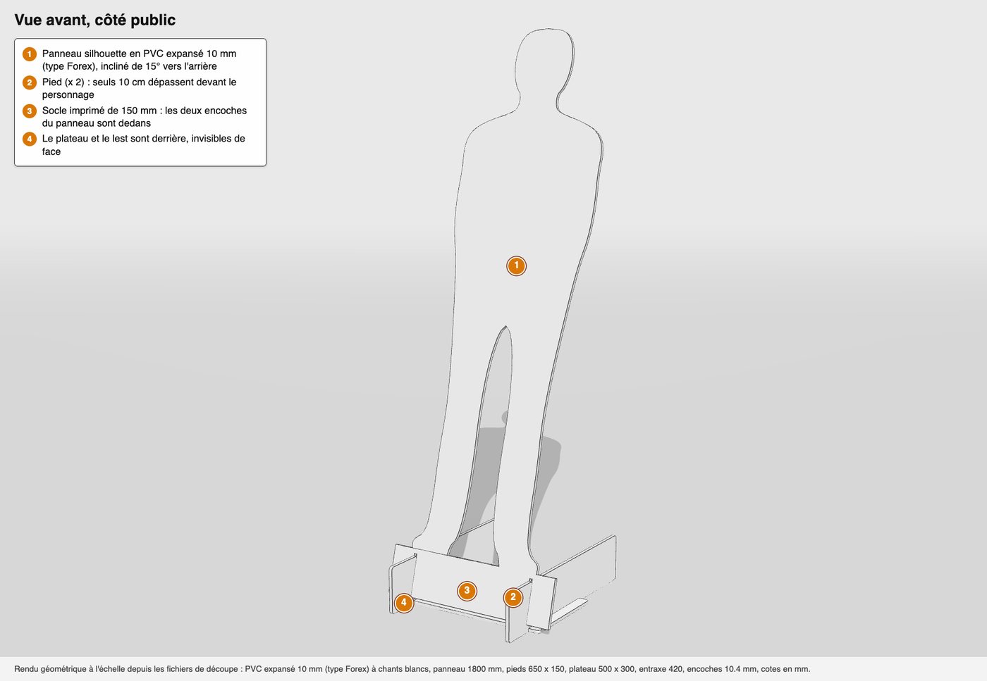
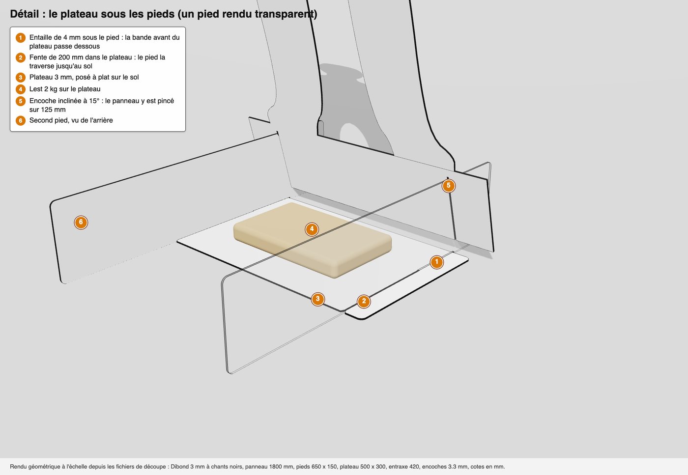
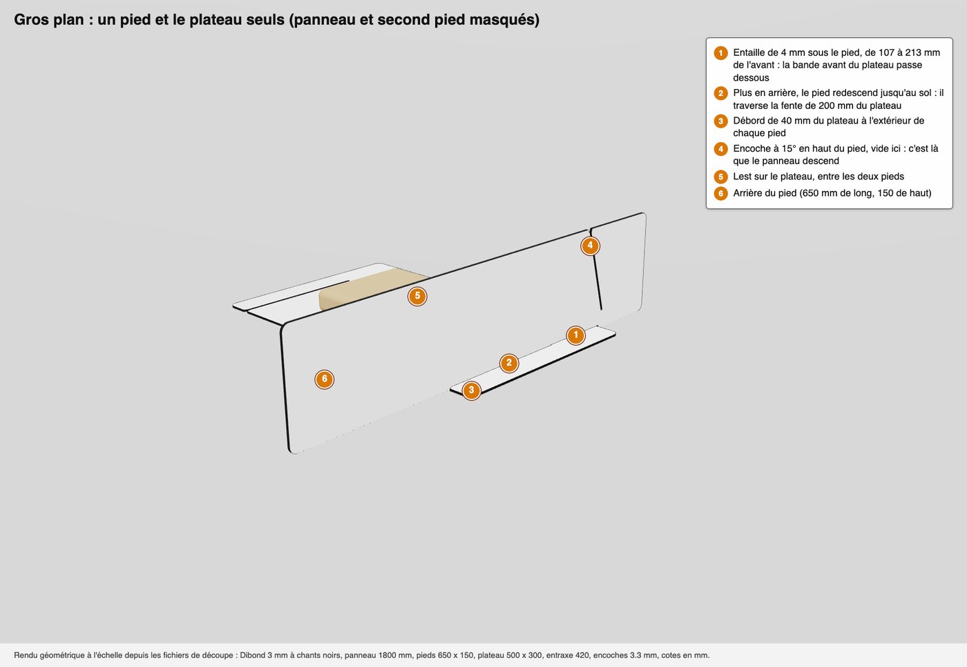
- two identical feet measuring 65 × 15 cm, with a notch angled at 15°;
- un ballast tray measuring 50 × 30 cm, which slides under the feet.
A 2 kg ballast (a sandbag, two bricks) is placed on the tray, behind the panel: it cannot be seen from the front.
Two materials, the same system
| Dibond 3 mm | 10 mm foam PVC | |
|---|---|---|
| Appearance | Aluminium composite, slim black edges, highly rigid | Thick white sheet, white edges, "object" appearance |
| 180 cm panel | 2,8 kg | 4,1 kg |
| Set of 4 parts, without ballast | 4,2 kg | 6,0 kg |
| Use | Indoor and sheltered outdoor, durable, washable | Indoor: trade shows, shops, events |
| Printing | Direct UV four-colour process | Direct UV four-colour process |
To compare materials in more detail, read Dibond, PVC or acrylic: which panel to choose.
Why it doesn't fall over
A classic silhouette stands on a strut: it withstands frontal wind, but topples forward at the slightest draught from behind. Here, three factors combine:
- The panel is tilted 15° backwards, like a free-standing photo frame. Its centre of gravity shifts back above the base, while the feet protrude only 10 cm in front of the character.
- The tray locks both feet together between them and widens the base footprint to 65 × 50 cm.
- The 2 kg ballast, hidden behind, finishes the job.
Tolerated wind before toppling, for a 180 cm panel:
| Version | Wind from the front | Wind from behind |
|---|---|---|
| Classic silhouette on strut | 20 km/h | 9 km/h |
| Life-size 3 mm Dibond, without ballast | 19 km/h | 19 km/h |
| Life-size 3 mm Dibond, 2 kg ballast | 24 km/h | 22 km/h |
| Life-size 10 mm PVC, 2 kg ballast | 27 km/h | 26 km/h |
These values are calculated from the dimensions and weights of the parts: they provide an order of magnitude, not a guarantee. For reference, an opening door generates 4 to 7 km/h, an entrance hall with automatic doors 10 to 18 km/h, a terrace 18 to 30 km/h.
Assembly in two minutes, without tools
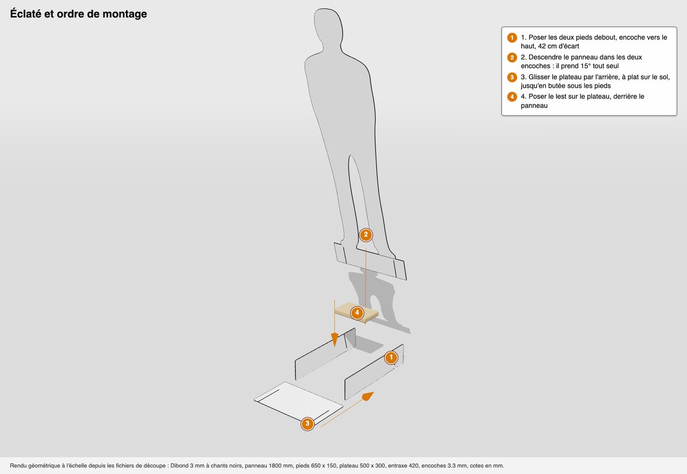
- Place the two feet upright, notch facing upwards, 42 cm apart.
- Slide the panel down into both notches: it tilts back 15° on its own.
- Slide the tray from the back, flat on the floor, all the way under the feet.
- Place the ballast on the tray, behind the panel.
Disassembly is carried out in reverse order. The standee can be reassembled as many times as needed, and both feet are interchangeable.
The process: digital cutting to the nearest tenth of a millimetre
The four parts are cut by a CNC machine from the same sheet as the panel. Three details ensure the stability of the whole assembly:
- Notches cut to the exact width of the panel, with a few tenths of play: the panel slides in without forcing and does not wobble.
- A chamfered entry, wider at the top: it guides the panel when lowered into the feet.
- A half-lap joint between the feet and the tray: the feet pass through two slots in the tray, which remains flush with the floor.
No screws, no glue, no extra fittings. On the cut itself, see what is contour cutting.
Assembly diagrams to download (PDF, A3 format, 1:10 scale): 3 mm Dibond version and 10 mm PVC version.
Dimensions and limits
- Panel height : up to 180 cm, giving a top edge at 176 cm from the ground once tilted. Beyond that, contact us.
- Width : up to 100 cm.
- Base of the cut-out : a solid strip of material is required to accommodate the two notches. The simplest solution is a 15 cm printed base, which can also carry text or a logo.
- Footprint : 65 × 50 cm. The top tilts back by 47 cm relative to the foot.
- Small sizes (child, animal, product): the same system, with shortened feet.
Files to supply
- High-definition artwork : cut-out full-length photo, illustration or brand mascot, at least 150 dpi at final size, with 5 mm bleed around the cut line.
- A vector cut path (PDF or AI). Alternatively, we draw it from the artwork, and the proof shows the cut line.
- Nothing else : the base, notches, feet and tray are added by us.
Use an image for which you hold the rights: your photo, your mascot, your product. Our guide explains how preparing your file.
Indoor or outdoor
10 mm foamed PVC is made for indoor use: trade shows, shops, lobbies. Heavier, it withstands draughts better. 3 mm Dibond is suitable for sheltered outdoor use, under an awning or in an entrance: it withstands rain. In both cases, not in open wind.
Order
The price is calculated by surface area on the product page life-size silhouette, without a quote: the cutout, its feet and its tray, with contour cutting as an option.